
After de-obfuscating the WRT120N’s firmware, I started taking a closer look at the code, which runs the now-defunct SuperTask! RTOS.
Thanks in no small part to copious debug strings littered throughout the code and some leaked Atheros datasheets, I made good progress in statically disassembling the code. The next step was to start debugging the system while exercising some of the router’s services.
The WRT120N does have a JTAG port (labeled J8), which appears to conform to the MIPS EJTAG standard header:
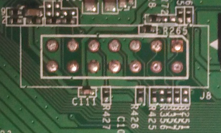
The WRT120N JTAG header
It didn’t work right out of the box though:
$ sudo openocd -f flyswatter2.cfg -f wrt120n.cfg
Open On-Chip Debugger 0.7.0 (2014-01-05-12:41)
Licensed under GNU GPL v2
For bug reports, read
	http://openocd.sourceforge.net/doc/doxygen/bugs.html
Info : only one transport option; autoselect 'jtag'
adapter speed: 6000 kHz
trst_and_srst separate srst_gates_jtag trst_push_pull srst_open_drain connect_deassert_srst
trst_and_srst separate srst_nogate trst_push_pull srst_open_drain connect_assert_srst
adapter_nsrst_delay: 100
jtag_ntrst_delay: 100
mips.cpu
Info : max TCK change to: 30000 kHz
Info : clock speed 6000 kHz
Error: JTAG scan chain interrogation failed: all ones
Error: Check JTAG interface, timings, target power, etc.
Error: Trying to use configured scan chain anyway...
Error: mips.cpu: IR capture error; saw 0x1f not 0x01
Warn : Bypassing JTAG setup events due to errors
Error: Error writing unexpected address 0xffffffff
Error: Error writing unexpected address 0xffffffff
Error: Error writing unexpected address 0xffffffff
Error: Error writing unexpected address 0xffffffff
It turns out that JTAG has been disabled in hardware and in software on the WRT120N. Luckily both were relatively easy to fix.
Patching the Hardware
One of the simplest ways to disable JTAG is to remove jumpers, and that’s exactly what has been done here:
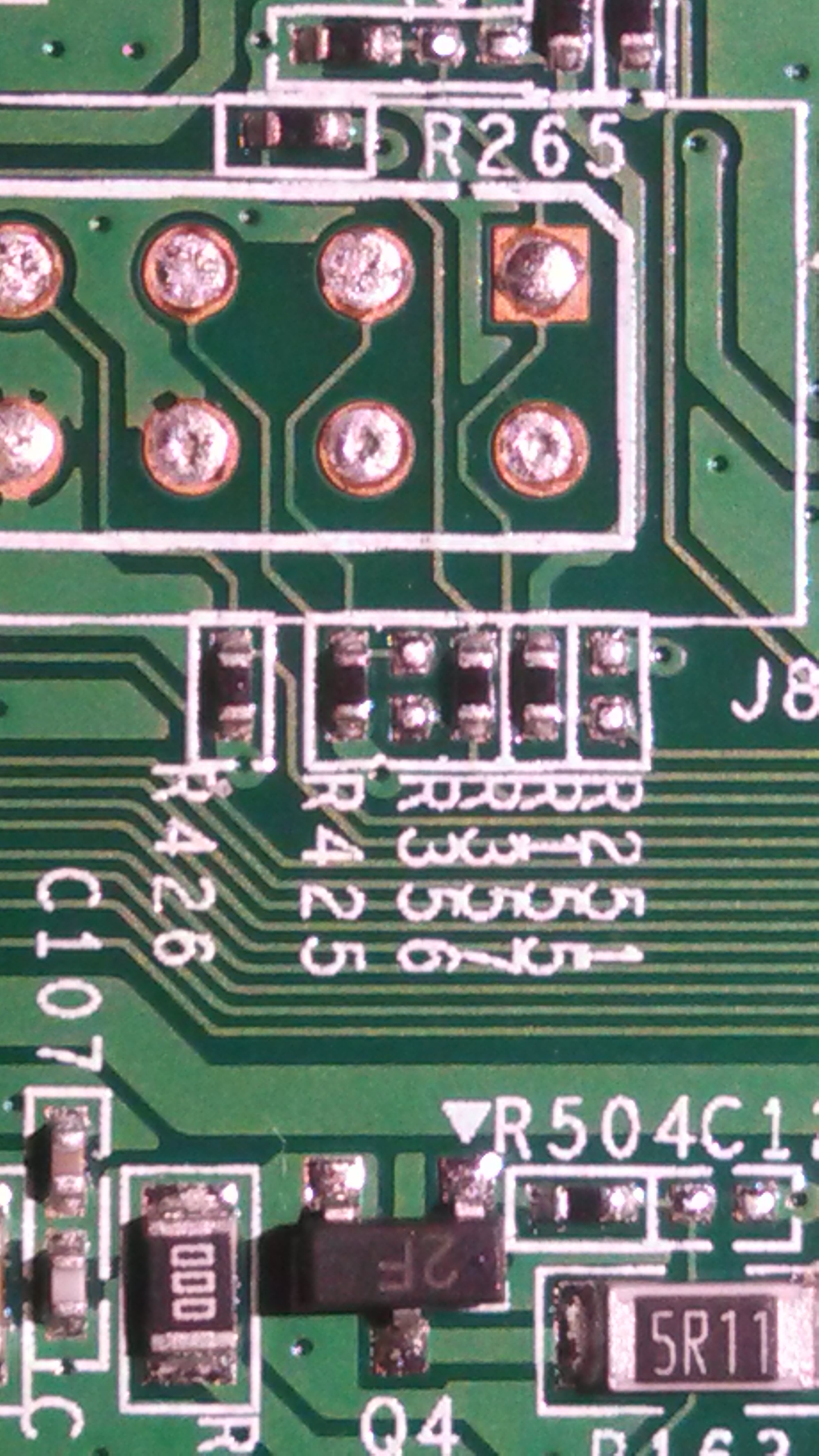
Missing R356 0-ohm jumper
The TDI pin on the JTAG header (pin 2) has been disconnected from the rest of the system by simply removing jumper R356. This was easily remedied with a quick solder blob:
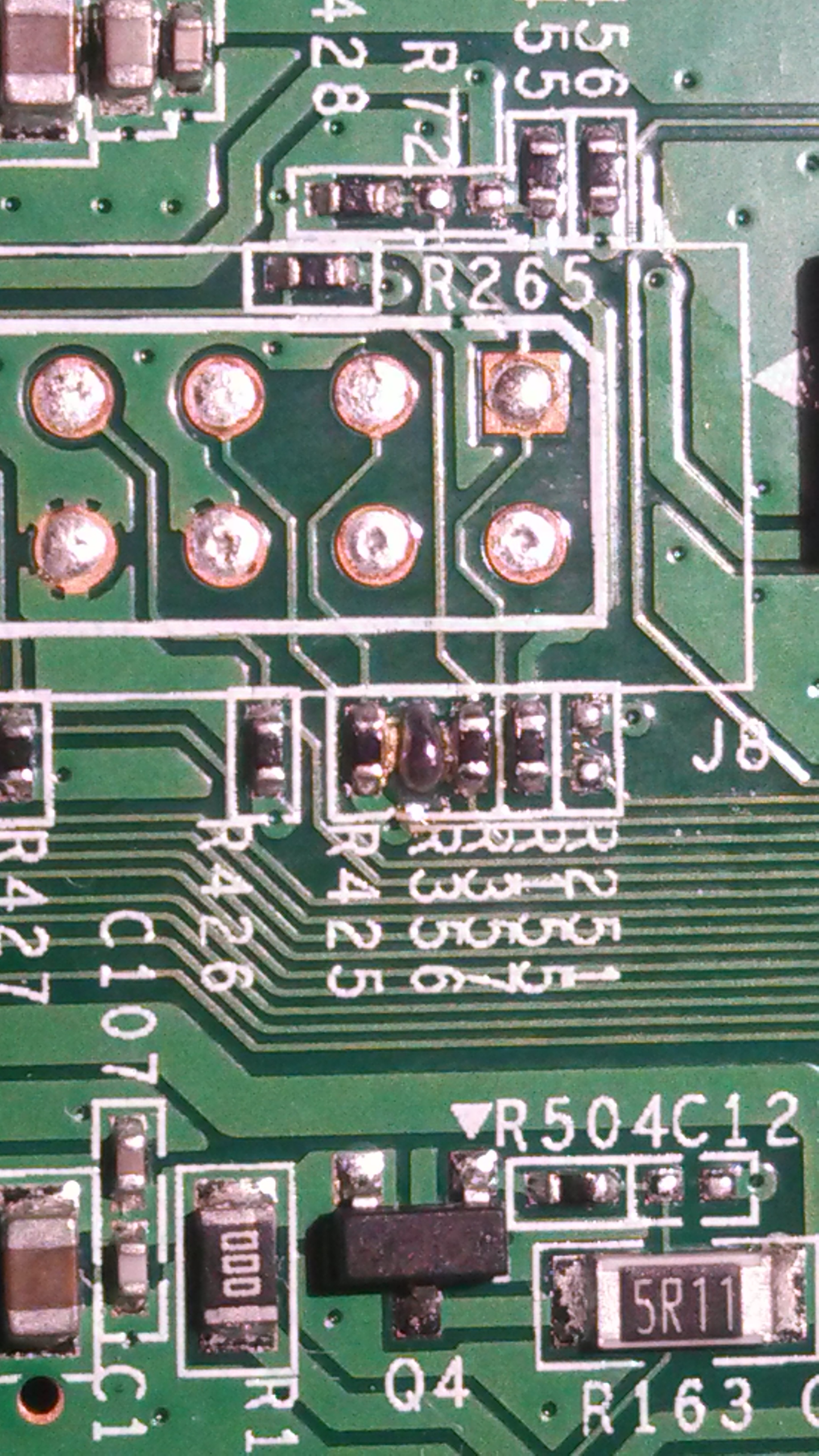
R356 solder blob
With TDI re-connected, I was able to reset the system and halt the processor over JTAG:
Open On-Chip Debugger
> reset init
JTAG tap: mips.cpu tap/device found: 0x00000001 (mfg: 0x000, part: 0x0000, ver: 0x0)
target state: halted
target halted in MIPS32 mode due to debug-request, pc: 0xbfc00000
Unfortunately, I quickly lost control of execution:
> resume
> halt
Failed to enter Debug Mode!
Halt timed out, wake up GDB.
timed out while waiting for target halted
in procedure 'halt'
After some probing, I found that this is due to the hardware design of the WRT120N: the reset button has been connected to the JTAG TDI pin on the AR7240 SoC. It is common for systems to allow JTAG pins to be re-configured as GPIO pins, so this is not un-heard of. However, this means that JTAG is likely being disabled in software.
Additionally, when depressed, the reset button asserts this pin low; the TDI line driven from my JTAG adapter also idles low. This means that whenever the JTAG adapter was connected to the JTAG header, the system thought that the reset button had been pressed.
I obviously didn’t want JTAG to be disabled, nor did I want the system continually resetting during a debug session. But, since I couldn’t magically redefine hardware pins, these were issues that had to be addressed in software.
Patching the Bootloader
The first firmware patch I needed to make was to the bootloader.
As seen previously, the bootloader checks the reset pin, and if asserted, it boots into a recovery image instead of booting the main image:

if(check_reset_button() != 0) goto load_main_image;
Since the JTAG adapter pulls the TDI line low, the bootloader wouldn’t even boot the main OS with the JTAG adapter connected; it thought the reset button had been pushed and loaded the recovery image instead!
There were two solutions to this problem. First, I could simply set a breakpoint on this conditional branch and change the register contents so that the recovery image is never loaded.
Besides being a PITA, this approach turned out to be impractical due to the following piece of earlier code:
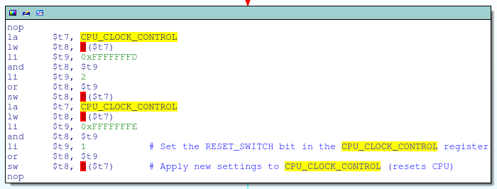
Setting the RESET_SWITCH bit in the CPU_CLOCK_CONTROL register
This code is executed very early in the boot process and is in part responsible for configuring the system’s PLL clock. Specifically, the code snippet above sets bit 0 (the RESET_SWITCH bit) in the CPU_CLOCK_CONTROL register; according to the datasheet, this generates a CPU reset, causing the debugger to lose control of execution:
This register [CPU_CLOCK_CONTROL] controls the clock and reset to the CPU. These bits are controlled by driver software…RESET_SWITCH reset[s] during clock switch trigger.
What this means is that I would have to enter JTAG debug mode after the PLL was configured, but before the reset button was checked; a race condition that was difficult to reliably to win.
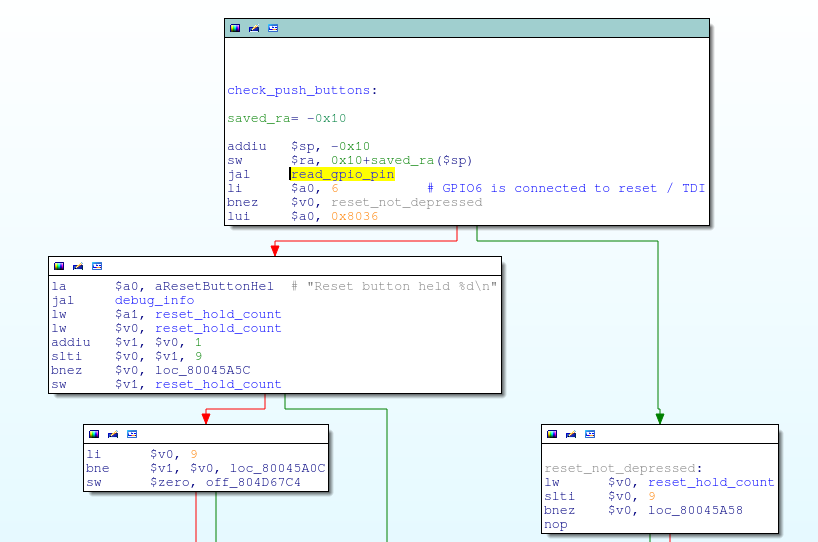
Instead, I opted to simply patch the bootloader on the flash chip. The check_reset_button function masks out bit 6 of the GPIO_IN register (aka, the TDI pin) by performing a logical AND with 0x40; if that pin is low, the function returns 0 (reset button depressed), else it returns non-zero:
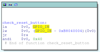
The check_reset_button function
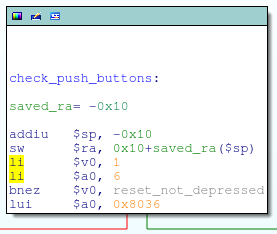
I changed this from a logical AND to a logical OR, ensuring that check_reset_button always returns non-zero regardless of the actual state of the pin. This is just a one bit change to the instruction opcode:
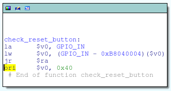
The modified check_reset_button function
Desoldering the flash chip and overwriting the bootloader with this patch got me past the bootloader and into the main OS:
> bp 0x800081ac 4 hw
breakpoint set at 0x800081ac
> resume
target state: halted
target halted in MIPS32 mode due to breakpoint, pc: 0x800081ac
However, JTAG debugging was killed shortly thereafter, and the serial console was spammed with “Reset button held…” messages:
Reset button held 0
Reset button held 1
Reset button held 2
Reset button held 3
Reset button held 4
Reset button held 5
Reset button held 6
Reset button held 7
Reset button held 8
Reset button held 9
...
Patching the OS
Something in the OS was disabling JTAG, and the culprit was found in the configure_peripherals function:
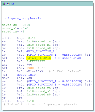
GPIO_FUNCTION_1.EJTAG_DISABLE = 1
This code is responsible for setting the EJTAG_DISABLE bit inside the GPIO_FUNCTION_1 register. According to the datasheet, this will:
Disable EJTAG port functionality to enable GPIO functionality; can be set to 1 to enable using GPIO_5, GPIO_6, and GPIO_7 as GPIO pins
This was easily fixed by simply nopping out the ori instruction that was used to set the EJTAG_DISABLE bit:

EJTAG_DISABLE bit patched
For good measure, I also went ahead and nopped out the function call to gpio_tris that configures GPIO#6 (aka, TDI) as a GPIO input:
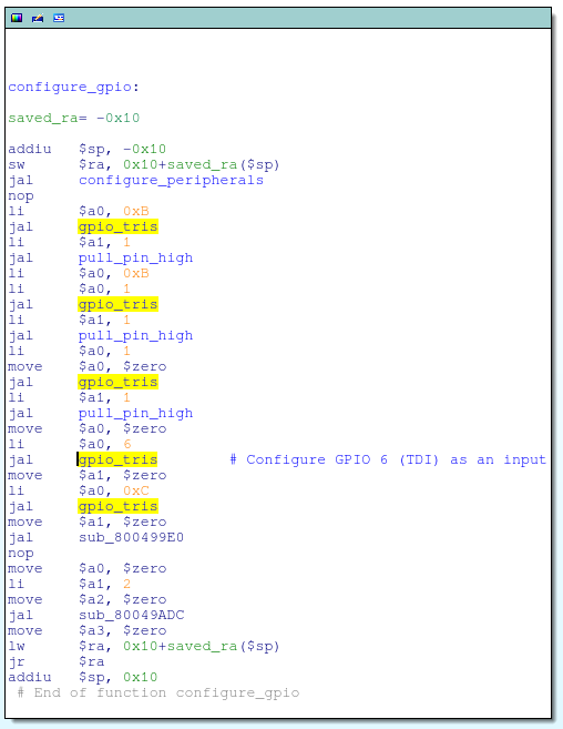
gpio_tris(GPIO6, INPUT);
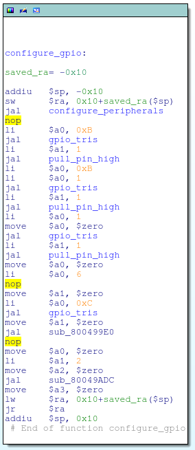
Call to gpio_tris nopped
And got rid of that pesky reset button check that was spamming my serial console as well:
if(read_gpio_pin(6) != 0) goto reset_not_depressed;
if(1 != 0) goto reset_not_depressed;
Re-building the Firmware Image
Having patched the OS, I needed to write it back to the flash chip. Not wanting to de-solder the flash chip yet again, I opted to apply the patches via a firmware update.
Since the OS image had been modified, I first needed to figure out the checksum for the firmware update file. It turns out that it is a standard CRC32 checksum that is stored in the firmware footer:
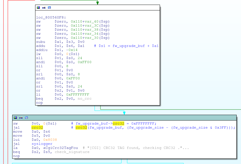
The crc32 function being called from cgi_upgrade
The checksum field itself is set to 0xFFFFFFFF at the time of calculation, and the checksum is calculated over the entire firmware update file, except for the board ID string at the very end.
So, putting everything together, I just needed to:
- Re-compress the modified OS image
- Concatenate the LZMA compressed web files and firmware footer with the compressed, modified OS image
- Re-obfuscate the firmware image
- Re-calculate and patch the checksum
I threw together a little script to automate this; it’s super hacky, but works so long as I don’t change the size of the decompressed OS image.
After buggering it up the first time, I recovered the system and flashed the modified firmware image through the router’s web interface. After a reboot, lo and behold, JTAG was up and running without issues:
> halt
target state: halted
target halted in MIPS32 mode due to debug-request, pc: 0x800045a4
> reg
===== mips32 registers
(0) zero (/32): 0x00000000
(1) at (/32): 0x804E0000
(2) v0 (/32): 0x00000000
(3) v1 (/32): 0x805BD6E4
(4) a0 (/32): 0x803D0000
(5) a1 (/32): 0x0000000A
(6) a2 (/32): 0x805BD57C
(7) a3 (/32): 0x806BD190
(8) t0 (/32): 0x80003F28
(9) t1 (/32): 0x00000000
(10) t2 (/32): 0x00000050
(11) t3 (/32): 0x807D7CA0
(12) t4 (/32): 0x00000109
(13) t5 (/32): 0x00000000
(14) t6 (/32): 0xEFFFFFFA
(15) t7 (/32): 0x00000001
(16) s0 (/32): 0x80A3E42C
(17) s1 (/32): 0x0000000A
(18) s2 (/32): 0x00000050
(19) s3 (/32): 0x80196100
(20) s4 (/32): 0xFEDFFE95
(21) s5 (/32): 0xB9DFDFDF
(22) s6 (/32): 0xFEFFDD37
(23) s7 (/32): 0xDEDFFBC9
(24) t8 (/32): 0x00000000
(25) t9 (/32): 0x3548A4A8
(26) k0 (/32): 0x0000FC03
(27) k1 (/32): 0xFFFFFFFE
(28) gp (/32): 0x804DA890
(29) sp (/32): 0x80820870
(30) fp (/32): 0x7EFFEFCF
(31) ra (/32): 0x80003FFC
(32) status (/32): 0x0000FC01
(33) lo (/32): 0x851EBB0A
(34) hi (/32): 0x0000031B
(35) badvaddr (/32): 0xACED8496
(36) cause (/32): 0x10004400
(37) pc (/32): 0x800045A4
>
I’ve placed a copy of the modified firmware image up on github, along with the script used to build it. Note that this will not patch the bootloader, although upgrading the bootloader via a firmware update does appear to be supported; I’ll leave that as an exercise to the reader. 😉