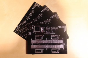
In preparation for our Embedded Device Exploitation classes, I’ve just released my latest project, the Gumbi board:
The Gumbi board provides a flexible USB interface to the real world in the form of 64 digital I/O pins – all controllable from the comfort of your Python shell, allowing you to rapidly prototype and create new tools for interfacing with external devices.
Take flashbin for example, an open source flash programmer I’ve written for working with external parallel flash chips.
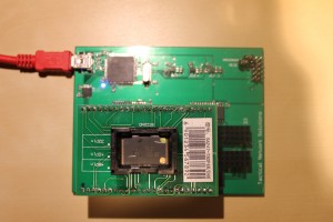
Although popular for firmware storage, parallel NOR flash chips are particularly difficult for hobbyists/hackers to work with because their interface typically requires 30 to 40 I/O pins (or more!). This tends to result in error-prone wiring that has to be re-wired whenever you need to interface with a different chip:
Using the Gumbi board however, everything can be defined (and re-defined) in software. Just plug the chip in, create a flashbin config file that defines the pin configuration for your target chip, and you’re ready to go:
The Gumbi API is written in pure Python, is portable across operating systems (although only tested on Linux for now), and easy to use. Here’s a simple example that can be used to blink an LED connected to pin 1 of the Gumbi board:
        from gumbi import GPIO

        io = GPIO()

        for i in range(0,100):
               io.PinHigh(1)
               sleep(1)
               io.PinLow(1)
               sleep(1)

        io.Close()
Here’s a slightly more interesting demonstration of using the GPIO mode to blink 32 LEDs in sequence:
        from gumbi import GPIO

        io = GPIO(voltage=3)

        try:
                print "Starting Gumbi LED test. Press Ctrl+C to quit."

                while True:
                        i = 1

                        # Loop through the first 32 pins on the Gumbi board
                        while i <= 32:
                                io.PinHigh(i)
                                io.PinLow(i+1)
                                i += 2

                        # Loop through the next 32 pins on the other side of the Gumbi board
                        while i <= 64:
                                io.PinLow(i)
                                io.PinHigh(i+1)
                                i += 2

                        sleep(2)

                        # Turn off all LEDs, in order
                        io.PinsLow(range(1, 65))

        except KeyboardInterrupt:
                pass

        io.Close()
The hardware for the Gumbi board was also designed with flexibility in mind. Gumbi can interface with chips at various voltage levels from 1.8v – 5v, and includes three on-board software controlled voltage regulators for 1.8v, 3v and 4.7v. If those don’t fit your needs, you can disable the on board regulators completely and supply your own external power.
There is also an expansion header that allows you to add more I/O pins, up to 128 in total. The number of available I/O is automatically detected by the firmware, so no firmware or software changes are needed to support additional I/O pins.
All students who attend our Embedded Device Exploitation course will receive (among other goodies) a Gumbi kit which they will be assembling and using during the firmware extraction portion of the class.
Although currently in beta, all of the schematics, design files, firmware and software are available on the Gumbi Google Code page. I will be delving in to some more details about Gumbi in the future and I have lots of fun projects planned, so keep an eye on the blog for updates!


